
A video tutorial is available for this topic.
Drillhole data needs to be imported into an internal drill hole database within your project file. This enables Spatial Integration to access drill data quickly and efficiently, as well as providing some quality checks.
Spatial Integration uses Drill Groups to maintain several logically separate drill databases. For example, you might want to keep planned holes separate from completed holes. Each group can be updated, removed, shown in the scene and symbolised individually.
Collar, survey and downhole interval data are loaded separately, each within a tabbed page in the Drill Manager. Source files can be CSV or any supported GIS format.
Loading Collars
The Drill Manager can be selected from the drill flyout menu.
First, select the active drill group from the dropdown box. There will always be one active group, which defaults to being called default. The plus button next to the group box allows you to add another drill group. A subtract sign will also be displayed when you have multiple drill groups, allowing you to delete a group and all the drill data associated with it.
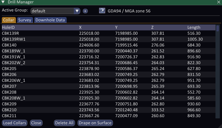
Click the Load Collars button. Make sure the data source type is correct, CSV or GIS, then use the browse button to find your collar file.
The contents of the file are displayed, including the column names and types. Spatial Integration will try to choose the correct columns to import using a set of rules, but you need to check the automatic selections and correct them when required.
If you don’t have collar elevations, you can deselect any elevation columns and drape the collars on an existing surface instead, after they are loaded. Deselect by clicking the Elev label and choosing the blank space at the top of the dropdown list.
If you are loading collar data from a GIS file, you also have the option of using the GIS geometry for X and Y locations, plus for the Z location in the case of a 3D GIS source. Elevation can then be specified by an attribute column, or by draping on an elevation surface after collars are loaded.
Dip and azimuth can also be included from the collar file, but this is optional. If dips are specified, please ensure the box at the top of the dialog box is checked if your dips are negative down.
Once you have selected the correct columns, click the Add button and the collars are loaded. Once loaded, check for messages (the envelope icon in the bottom right) to see if there were any problems during the process. These will help you track down problems in the source file and fix them.
Drillholes required a projected coordinate system to calculate the drill trace. You can set the Coordinate Reference System (CRS) using the button at the top of the dialog. If no CRS is set, then the CRS of the view will be assumed.
If you need to drape collars on a surface you can use the Drape on Surface button along the bottom of the dialog. You must already have defined an elevation surface to do this. You can re-drape collars at any time as it will trigger drill traces and downhole data positions to be recalculated.
You can delete all the collars in the active group using the Delete All button. If you delete a collar, all the surveys and downhole data associated with that collar will also be deleted.
Loading Surveys
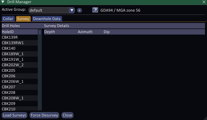
Surveys are loaded in a similar way to collars. Select the Survey tab and make sure the correct drill group is made active.
Click the Load Surveys button to load survey data. Follow the same process, ensuring that the HoleID, Depth, Dip and Azimuth columns are correct. The azimuth should be correct for the CRS you have selected for this drill group. Make sure the sign of the dip checkbox is correct and click the Add button.
You will be taken back to the Drill Manager dialog while your surveys load. Once complete, you can select a drill collar from the list along the left of the page and review all the surveys assigned to that hole.
Any dip and azimuth values that were loaded along with the collars are given a depth of zero and will appear here in the Survey page along with the rest of the surveys.
The trace of drill holes will be recalculated whenever there is a change to the collar position or a survey. You can also trigger this recalculation by clicking the Force Desurvey button.
Load Downhole Data
Go to the Downhole Data tab to load your downhole data. Again, ensure the correct drill group is active, then click Load Downhole Data. Choose your data source as CSV or GIS, then click the browse button and find your downhole data file.
Spatial Integration supports two kinds of downhole data, selected with the Data Type radio buttons at the top of the dialog:
- Interval data describes a length of the hole and has both a From and a To depth. Assays, lithology and other logged intervals are of this kind.
- Point data describes a single position down the hole and has only a single depth. Structural measurements, geotechnical picks and spot readings are of this kind.
For interval data, make sure that Spatial Integration has picked the correct HoleID, From, and To fields. For point data, only the HoleID and a single Depth field are required. The generated layer name is based on the source file name, but you can change it if desired by typing in the edit box. This is recommended if the generated name is long or ambiguous.
Load as many downhole data tables as you need. A typical drillhole group would have one interval table for assays, another for lithology, and one or more point tables for structural measurements.
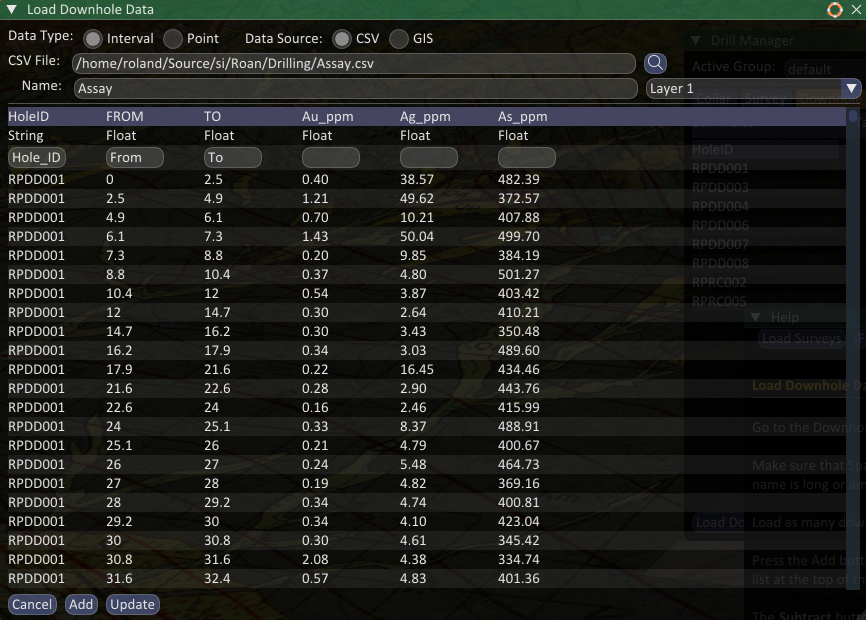
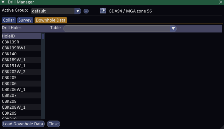
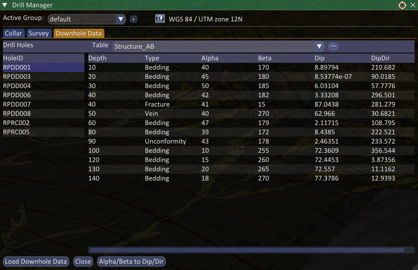
Press the Add button and you will be returned to the Drill Manager, where you can select a drill hole from the list on the left hand side and see the downhole data associated with that hole. Select the table you want to see from the dropdown list at the top of the page.
The Subtract button next to the table selector allows you to delete the current downhole table. You cannot delete the last drill group.
Structural Measurements
Structural measurements are loaded as a point table. Each row records a single depth together with the orientation of a plane, most commonly as a dip and dip direction.
Some downhole surveys record structure as alpha and beta angles relative to the core axis rather than as true dip and dip direction. If your point table contains alpha/beta columns, use the Alpha/Beta to Dip/Dir button along the bottom of the Downhole Data page to convert them. The tool reads the desurveyed orientation of the hole at each measured depth and writes new dip and dip direction columns into the table, ready to be displayed with the Structure visualisation.
Note that loading drill holes will not make them appear in the scene until you add them. Select Add Drill Group from the drill flyout menu, then select the desired drill group.
Spatial Integration will automatically install visualisations for Collars, Drill traces and Discs. The collar and trace visualisations are ready to use immediately, while the disc visualisation needs to be configured to be meaningful. Additional visualisations, such as Graph and Structure, can be added from the layer flyout menu.
Drill hole display is the subject of another tutorial.