A 3D shape is typically created in another application and exported as an Object Wavefront file, DXF or similar, usually just as geometry without colours, normals etc. It has a fixed position in space that is encoded in the file.
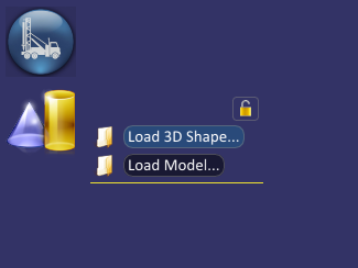
Spatial Integration will apply a series of processing steps, some of which are optional, to make the file more efficient for 3D rendering and allow you to change colours. Load a 3D Shape using the menu below:
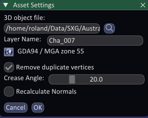
The Asset Settings dialog below will be displayed. First, select your file. The layer name will be automatically suggested using the filename, but you can change it here if desired. We suggest keeping the layer name short, but meaningful.
Multiple file selection is supported using the CTRL and SHIFT keys in the usuall way. If you select multiple files then the layer names will be assigned automatically using the file names and can’t be defined here during the inital load.
Select the CRS for the layer coordinates. If there is a .qpj projection file with the same name as the source file in the source directory, then Spatial Integration will pick up the CRS automatically. QGIS and Spatial Integration will write qpj files when a CRS is defined, so this normally only has to be done once. If multiple files have been selected, then the CRS you choose will be assigned to all of them.
Remove duplicate vertices
3D graphics are usually rendered as a series of triangles. The triangles are defined by vertices, with mutliple triangles using each vertex when triangles abutt each other. Rather than repeating vertices, we can keep a list of unique vertices and define the triangles using indexes into the vertex list. This saves a lot of memory and renders faster because each vertex only has to be transformed once. There is also a single face normal associated with each vertex, so that normal is then made to be an average of all the face normals using that vertex, which gives a smooth appearance across the surface. Many applications export files with vertices repeated for every triangle, which is less efficient and renders with a faceted appearance.
If selected, this option will remove duplicate vertices and assign an average of the face normals to the vertex, which will render as a smooth surface. If the angle between faces is too great then we want the surface to be rendered as a sharp edge instead of a smooth surface, so if the angle between faces exceeds the Crease Angle then the vertices are not combined.
Recalculate Normals
Normals are calculated if not already present in the source file and rotated to the scene CRS if required. If you suspect a problem with normals (the lighting looks wrong when rendered to the screen), then you can force recalculation of the normals as a final step in the processing.