
The graticule is a reference grid drawn through your scene, with labels showing real world coordinates. It gives you a quick sense of scale, position and orientation without having to measure anything.
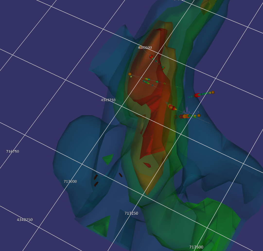
The grid is drawn in the coordinates of your project CRS, so the labels are the same eastings, northings and elevations you see in the status bar.
Showing the Graticule
Toggle the graticule using the grid button on the status bar, or by pressing the G key.

The status bar buttons are, from left to right: legend, measure, screenshot, graticule, perspective view and orthographic view.
The graticule is only available in a Projected view. In a geographic (latitude / longitude) view the button is disabled, because a grid measured in world units is not meaningful there.
The graticule setting is remembered between sessions.
How the Grid is Drawn
The grid planes are drawn through the view centre, which is the point the camera rotates about. Only one plane is shown at a time, chosen automatically from your viewing direction:
- Looking down (steeper than 45 degrees), a horizontal plane carrying the X and Y grid lines is drawn at the height of the view centre.
- Looking more from the side, a vertical plane is drawn instead. It carries the elevation grid lines plus the X or Y lines, whichever plane best faces the camera.
The grid follows the camera. As you zoom in and out, the grid spacing changes so that the grid always stays readable, and as you pan the grid is rebuilt around the view centre.
Positioning the Grid
Middle mouse click on an object to recentre the view on that point. The graticule recentres with it, so this is how you position the grid where you want it. Recentring on objects at different heights moves the horizontal grid plane up and down, letting you place it at the elevation that suits what you are looking at.
The grid is a real object in the scene, not an overlay drawn on top. It is obscured by anything closer to the camera, just like any other feature, which is what makes it read as part of the scene and helps you judge what lies in front of or behind the grid plane.
Configuration
Graticule settings are found in the Configure dialog, opened from the Tool flyout, on the Visualisation tab.
Grid colour sets the colour of the grid lines. The change is applied to the scene immediately.
Grid label colour sets the colour of the coordinate labels, independently of the lines. Labels are easier to read when they are a little brighter than the grid itself, which is the default. This change is also applied immediately.
Label grid axes E, N and RL appends a suffix to each label showing which axis it belongs to: E for easting, N for northing and RL for reduced level. Turn it off if you prefer bare numbers, or if the axes do not read as eastings and northings in your projection. The labels are rebuilt when you change this, so the grid flickers briefly.
Number of grid lines is a target, not an exact count. Spatial Integration divides the height of the visible view by this number to get a rough grid spacing, then rounds that spacing up to the nearest sensible number: 1, 2, 2.5 or 5 times a power of ten. This is why the labels always read as round numbers such as 250, 500 or 1000 rather than awkward values like 337.
Because the spacing is rounded, the number of lines you actually see varies as you zoom, and is usually a little less than the target. A target of 5 typically gives between 3 and 5 lines across the view.
Use a smaller number for a coarse, uncluttered grid, and a larger number for a finer grid with more labels. The default is 5.
Changing the number takes effect straight away while the graticule is displayed.